


3D-Print Your Own Lab Clamps
- Mark Schober
- Aug 14, 2020
- 7 min read
Updated: Apr 29, 2021
Clamps! You can never have too many, and a great table clamp is indispensable when setting up labs in the physics classroom. But table clamps sell for $50-$100 each, so I set out to design a 3D-printable table clamp that was robust, multifunction, and low cost. Along the way, I designed a variety of other clamps as well that I've shared below. You don't have to print out many clamps before you've earned back your investment in a 3D printer.

A disclaimer right up front: 3D printed plastic clamps will never be as strong and durable as metal clamps. Although I haven't had any of my 3D-printed clamps fail, I haven't let my students go wild with them, either. For most introductory physics lab activities, these clamps are stable, solid, and strong enough to get the job done, as long as you tighten the bolts with attentiveness to the strain you are putting on the plastic. If a clamp fails and your lab apparatus falls down, don't blame me!
If you have a 3D-printer, great! If you don't, here's how you get a 3D printer:
You: Dear person who holds the purse strings, I need 16 table clamps.
Money Person: How much? You: $1600. Money Person: Seriously? No. You: Okay, here's an alternative: I need a 3D printer that I can use to print all the clamps I could ever need while providing my students with the opportunity to learn how 3D printing works and enable them to print their own designs. Money Person: How much? You: $1600. Money Person: Sold!
Basics of 3D Printing
If you're new to 3D printing, here's the workflow:
Start by designing a 3D object using 3D design software such as TinkerCAD, SketchUp, or OpenSCAD. Alternatively, you can download 3D files, like the ones I've provided below, or those on websites like thingiverse.
Once you've designed the object and saved it in the program's native format, you need to export the 3D object as an .stl (STereoLithography) file.
Next, you need slicing software such as Cura that will read the .stl file and turn it into a toolpath for your specific 3D printer. This is where you can adjust the print quality settings as well, determining the thickness of each layer or the percentage fill inside the object, for example.
All of the software I use is free.
Printer Details
I printed all of these clamps on a Lulzbot Mini 3D printer. At $1250, it is more expensive than many printers on the market, but it works so well. Cheaper printers will get the job done, but they often take more of your time to get them and keep them properly adjusted to work reliably while risking more failed prints. The Lulzbot has a heated platform, it self-levels, and its 8x8x8" print volume is plenty big for all of these lab clamps.

I printed everything using PLA filament. ABS plastic would be stronger, but we don't have great ventilation in our 3D printer room, so we've put the ABS on the shelf until we upgrade our ventilation. I experimented with a variety of print settings and I settled on printing layers .25 mm thick, with walls 1 mm thick and a fill of 30%. This gave me good balance between strength and print speed.
I have not yet experimented with annealing the 3D prints, which should make them up to 30% stronger according to what I've read. Annealing involves reheating the prints in an oven above the glass temperature of the plastic, but below the melting temperature of the plastic. This allows the internal stresses in the print to release while strengthening the bonds between print layers.

In addition to the 3D-printed parts, I used 5/16" nuts and bolts to form the clamps. For lab rods, I've gotten some 3/8" solid rods from steel suppliers on eBay. If they have the length you want at a good price, you're set. For me, the low cost winner is 1/2" electrical metallic tubing (EMT conduit). It's inexpensive and easy to cut. I prefer cutting with a pipe cutter, because it leaves a much smoother cut than a hacksaw. I designed all of the clamps to handle this size of pipe, which is pretty large in diameter compared to most lab rods. The teardrop shape of the holes in the clamp is to provide three contact surfaces for any size of lab rod, resulting in a stable clamping configuration.
Printer Settings

I experimented with a variety of print settings and I settled on printing layers .25 mm thick, with walls 1 mm thick and a fill of 30%. This gave me good balance between strength and print speed. In my tests, I went from a 20% fill with thick walls (on the left) to a 30% fill with thinner walls (on the right). The latter printed more quickly and was every bit as strong.
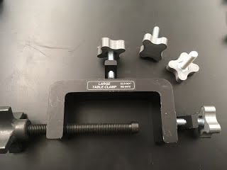
Table Clamp
I had great fun prototyping this clamp, eventually coming up with something that prints well, is strong, clamps to a table as thick as 1.75", and handles rods as large as 1/2" EMT conduit.


Editable OpenScad file: Table Clamp
Printable .stl file: Table Clamp (Scale the thickness of the clamp to 27 mm in your slicer software.)

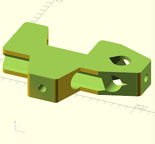


You'll also need to print three bolt handles for 5/16" bolts (file below). The bolts for clamping the rods are 1.5" long, and the bolt for clamping to the table is 3.5" long. I spin a nut two or three twists on to the bolt, apply a dab of hot melt glue to the head of the bolt, and then use a hammer to pound the head of the bolt into the printed bolt handle. The nut protects the threads at end of the bolt which would otherwise be damaged by the hammer. For each bolt, there is a recessed hexagonal hole to hold the nut in the 3D print. I insert the bolt through the print, spin the nut on, apply some hot glue to the sides of the nut, and then pull the bolt to set the nut into the hexagonal hold.

The bolt that attaches the clamp to the table needs something attached to the end of the bolt to avoid damage to the surface. With the bolt threaded through the nut fixed in the 3D print, add a second nut at the end of the long bolt with a couple of twists, add some hot glue to the bolt just under the nut, and then spin the nut down the bolt until it becomes stuck in the hot glue.
Adding a rubber pad for additional friction to the portion of the clamp that sits on the top of the table dramatically increases the clamp's stability.
Prototyping process:

From left to right, I started with a 1.5" thick version of the clamp that could only attach a lab rod vertically. I printed with different amounts of fill until I found that 30% fill made a big difference in strength while still printing relatively quickly. I next added the ability to clamp a rod horizontally to the table. In the third prototype, I added some angled elements to increase the strength of the clamp, and it made a big difference in the clamps' stiffness. My final design included angles into the horizontal clamp while adding a hole for clamping sideways. In particular, I can use this hole to attach a pulley. I like the functionality and the look of the final design.
Boss Head Clamp/Right Angle Clamp
I had initially printed these as the intersection of two cylinders at right angles, but found adding the extra material to form a flat base made the print work much better. You'll also need to print two 5/16" bolt handles for each clamp. The bolts themselves are 1.5" long.
Boss head clamps can be purchased pretty inexpensively on eBay, but printing them is very satisfying. Also, if you want to go with the 1/2" EMT conduit for your lab rods, you'll need to print these, because most boss head clamps are too small to accommodate the conduit.
Editable Open SCAD file: right angle clamp
Printable .stl file: right angle clamp (scale to 34.9 mm high in slicing software)


Tripod Ring Stand Base
Note that there is an inherent weakness in the design of this clamp. Unlike the other clamps I've designed, where tightening the bolt places stress parallel to the 3D printed plastic strands, in this design the bolts that hold the legs place a force on the clamp that tends to pry the layers of the 3D print apart. This print would greatly benefit from being annealed in an oven before being sent to work.
You could cut the legs to whatever length you like. The legs in the picture are 10" long.
Editable OpenSCAD file: ring stand base
Printable .stl file: ring stand base (scale to 80.2 mm high in slicer software)


Pendulum Clamp
You can easily get by without this clamp, but once you get the 3D printing bug (and you've got your printer working smoothly) you'll want to outfit your entire lab with all those crazy clamps you would never normally purchase!
The advantage of the pendulum clamp is that it is easy to adjust the length of the string for a simple pendulum while having the upper end of the string at a fixed location (which isn't true for a string wrapped around a horizontal rod).
Editable OpenSCAD file: Pendulum clamp
Printable .stl file: pendulum clamp (scale to 128.6 mm high in slicer software)


Pulley
At this point, I've only got the pulley itself, which can be mounted on an R4zz 1/4" x 5/8" x .196" bearing that I've mounted on a quarter inch bolt. I secure the bearing with two nuts. By twisting one nut into the other, they lock each other into place. The bolt can be clamped into the table clamp or the boss head clamp for all kinds of applications. I chose a ten-spoke design, the same as Pasco's smart pulleys, so that you could use it with a photogate and track the rotational motion of the pulley. I have a student designing a yoke to turn this into a pulley clamp. When we get it finished, I'll get it posted.
Editable OpenSCAD file: pulley
Printable .stl file: pulley (Scale to a diameter of 50.8 mm in slicing software.)


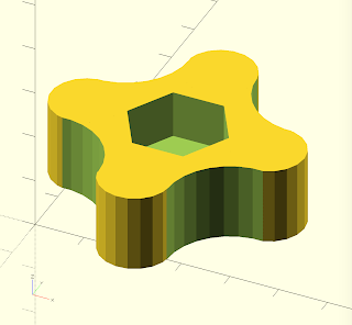
5/16" Bolt Handle

All of the clamps I've designed are for 5/16" bolts. You'll need a lot of these.
Editable OpenSCAD file: 5/16" Bolt Handle
Printable .stl file: 5/16" bolt handle (Scale to 12.7 mm high in slicing software)
3/8" Bolt Handle
We had a number of the handles from our Pasco table clamps break for whatever reason. I bought 3/8" bolts from the hardware store and printed handles for the bolts. The clamps are as good as new.
Editable OpenSCAD file: 3/8" Bolt Handle
Printable .stl file: 3/8" bolt handle (Scale in slicer to 12.7 mm high.)

Another Approach: Casting Resin
I developed a different clamp for the overhead metal racks in our physics labs consisting of an oval anchor and a knob attached to an eye bolt.


I needed so many copies of the same thing that I printed a few copies of the parts, made a silicone mold of the parts, and then cast resin copies of the parts using materials from Alumilite.


The polyurethane copies captured all of the detail of the layering in the original 3D print.
I hope you'll give 3D printing lab clamps a try. And, if it's more than you have time to get into, send a student to this page and encourage them to start printing some clamps!
Originally posted to my previous website June 4, 2017